uk-listings
Choosing a low-voltage synchronous marine alternator for a newbuild or mid-life retrofit involves far more than checking the nominal voltage on a quote. In modern 60Hz maritime power distribution architectures, an unverified voltage mismatch between the specified generator head and the vessel’s switchgear can trigger severe operational delays, costly engineering rework, and potential safety hazards during site commissioning.
Equipment packagers, marine architects, and system integrators must systematically audit every core electrical parameter long before physical hardware arrives at the shipyard floor. Partnering with a specialized component developer like EvoTec Power ensures that marine power conversion hardware aligns flawlessly with rigorous project specifications.
By conducting a thorough technical audit covering line-to-phase voltage relationships, terminal lead configurations, grounding network topologies, and dynamic regulation capabilities, procurement teams can completely eliminate major voltage integration errors and safeguard shipboard infrastructure.
Matching Line Voltage and Phase Voltage Relationships
The first checkpoint during technical verification involves confirming that the nameplate output line voltage and equipment phase voltage strictly correspond to the project’s single-line electrical drawings. In standard commercial 60Hz marine power distribution grids, a nominal 480V line-to-line output configuration corresponds directly to a 277V line-to-neutral phase arrangement. This relationship is derived from dividing line voltage by the square root of three in a standard three-phase wye system.
Assuming that an electrical machine automatically accommodates specific single-phase loads without verifying physical winding design creates major integration hazards. Delta systems or isolated neutral arrangements yield completely different phase relationships. When specifying a generator head engineered for a 480V generator installation, engineering teams must verify that the internal electromagnetic architecture yields balanced voltage output across all three phases, even under severe unbalanced load profiles.
Unbalanced auxiliary hotel loads or single-phase lighting circuits connected between line and neutral terminals can induce severe phase voltage unbalance if winding pitch and flux distribution are not properly designed. Verifying these voltage relationships on preliminary technical datasheets prevents unexpected sags and ensures downstream switchgear operates smoothly within design parameters.
Winding Lead Configurations and Connection Flexibility
Beyond verifying line and phase voltage ratios, buyers must carefully examine the terminal box arrangement, specifically defining the total number of stator winding leads and the factory-preset connection scheme. Modern marine alternators are frequently engineered with 12-lead reconnectable stators, granting system integrators maximum operational flexibility during field installation, retrofits, or regional power adaptations. A 12-lead terminal configuration enables a 480V generator to use a series star (Wye) layout for 480V/277V service, while allowing reconfiguration into parallel star or series delta layouts to accommodate alternative voltage standards if project requirements evolve.
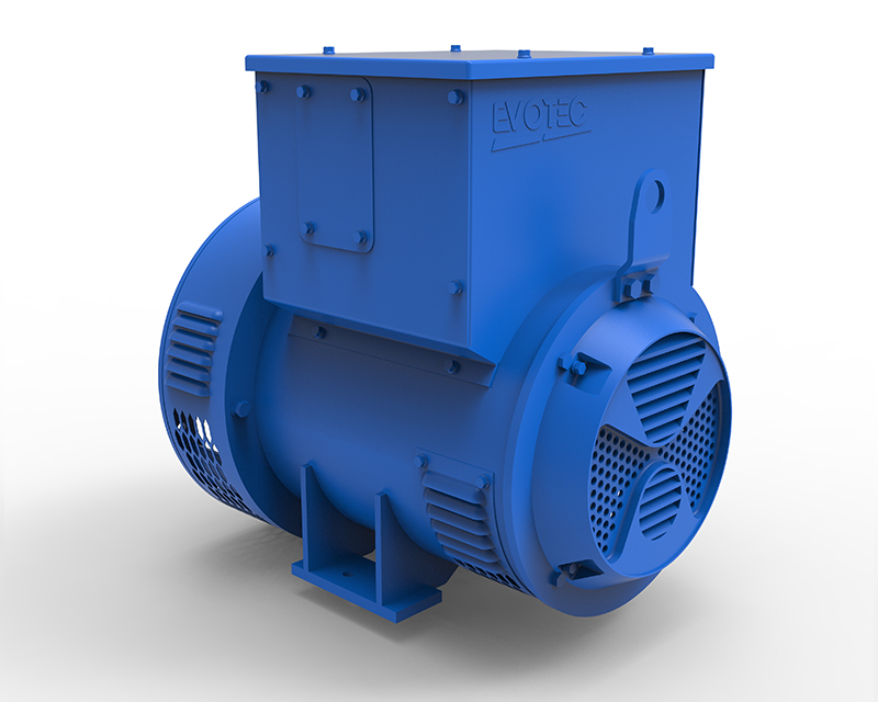
The TCM188 series engineered by EvoTec Power provides a primary example of this adaptability, featuring flexible terminal leads alongside Class H thermal insulation and IP23 enclosure protection. Clarifying whether the unit ships from the factory pre-connected in a series-star arrangement or requires manual jumpering drastically streamlines onsite wiring workflows, reduces labor hours, and eliminates potential connection errors during terminal wiring.
Aligning System Grounding Topologies and Protection Relays
System grounding topology represents another crucial engineering factor that dictates operational safety, insulation stress, and fault isolation protocols across the vessel. Maritime power networks utilize a variety of grounding philosophies, including high-resistance grounding (HRG), direct solid grounding, or ungrounded floating IT systems that are heavily favored on commercial cargo ships to maintain uninterrupted operation during a single line-to-ground fault. The selected grounding scheme directly influences the dielectric stress imposed on the alternator’s neutral point and stator windings during transient fault conditions.
Buyers must confirm that the neutral terminal construction and internal insulation barriers are built to withstand the specific grounding methodology utilized on board. Furthermore, ground-fault protection systems—such as zero-sequence current transformers or neutral voltage displacement relays—must be precisely coordinated with the alternator’s damage curves. Matching the machine’s physical insulation integrity with the vessel’s overarching grounding architecture prevents premature insulation breakdown and ensures protective relays execute controlled isolation before thermal damage occurs.
Evaluating AVR Voltage Regulation and Cable Drop Compensation
Extensive cable runs between marine generator heads and centralized main power switchboards naturally introduce feeder impedance and line voltage drops, especially during the starting of heavy inductive motor loads like bow thrusters or ballast pumps. To maintain unwavering busbar voltage stability across extensive distribution networks, procurement specialists must evaluate the actual performance of the Automatic Voltage Regulator (AVR). Modern digital AVR hardware offers a wide voltage adjustment range and exceptional transient recovery speed.
The TCM188 series maintains a steady-state voltage regulation characteristic of ±0.5%, with options for manual voltage adjustment potentiometers and parallel droop current transformers for multi-unit synchronization.
In addition, line-drop compensation features allow the AVR to dynamically boost exciter field current in proportion to rising load currents, effectively neutralizing reactive voltage drops along long feeder cables. Ensuring that the excitation controller maintains terminal voltage within tight limits guarantees that sensitive bridge navigation equipment, automation systems, and communication electronics remain fully shielded from harmful voltage dips and harmonic fluctuations during routine operations.
Marine Environmental Protection and Capacity Verification
In addition to electrical parameter alignment, marine applications require robust physical protection and realistic capacity evaluations to ensure long-term durability in chemically aggressive ocean environments.
Generator heads operating in shipboard machine rooms are continuously exposed to airborne moisture, salt fog, and diesel exhaust fumes. To prevent microscopic saline particles from degrading internal electrical insulation, advanced marine alternators incorporate specialized triple-proofing coatings—including anti-rust, anti-fungal, and anti-salt fog varnishes—applied directly to stator and rotor windings via vacuum pressure impregnation. Furthermore, nominal capacity must be evaluated alongside power factor, duty cycle, and motor-starting inrush.
When sourcing a compact component to support a 25kva generator setup, verifying the output capacity across the machine’s 18 to 40 kVA range under actual ambient marine temperatures ensures adequate operating margins. Auditing line-to-phase voltage proportions, terminal lead reconnectability, grounding compatibility, and dynamic AVR compensation guarantees seamless integration between the prime mover and the vessel’s primary power distribution network.